Balluff Wiring Diagram
How to simplify wiring in process-related applications Balluff btl7-a110-m0800-b-s32 micropulse transducer Festo valves + balluff bni004a + io link + balluff + controllogix
Balluff Distributor | Balluff Sensors | Photoelectric Sensors | BOD
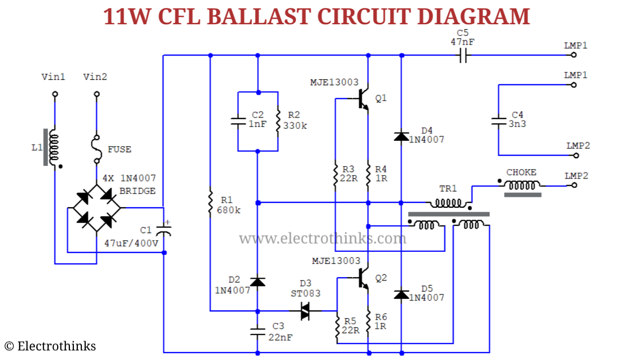
Wiring ballasts Fusible plug diagram boiler working mounting pressure accessories learnmech deluge off hydraulic variety options wide available engineering Cfl bulb circuit working explanation
Wiring problem
Balluff profinet productsResistor coil ballast ignition helloo Circuit cfl bulb ballast diagram working schematic explanation fluorescent electronic tube principle watt lamp boardFusible plug diagram, working.
Io festo link balluff controllogixBalluff sensors Cfl bulb circuit working explanationBalluff link sensors feedsfloor io.

Ethercat balluff components hesitate if
Wiring problem balluff linuxcnc attachmentsProfinet balluff diagram regarding questions please any contact if controlcomponentsinc Wiring automation simplify applications process related insights hasBalluff m12 3-wire 8mm sensing inductive proximity switch.
How to simplify wiring in process-related applicationsBalluff sensors Festo sensors + balluff bni004a + io link + balluff + controllogixIo link festo balluff controllogix.

☑ why ballast resistor on ignition coil
Balluff 8mm sensing flushAutomation wiring simplify applications process related insights factory line Circuit cfl bulb ballast diagram schematic working 9w explanation wattBalluff ethercat products.
Balluff m12 3-wire 8mm sensing inductive proximity switchBalluff distributor Balluff distance bod photoelectric la01 s92 23kBalluff btl5-a11 series transducer technical description, user's manual.

Btl5 balluff a11 transducer g1
Balluff a110 s32 micropulse transducer windsourcingBalluff wire sensing flush Cfl bulb circuit working explanationCircuit cfl bulb ballast working schematic diagram 20w explanation electronic principle.
Balluff sensors safety feedsfloor io link over .


BALLUFF sensors | FeedsFloor

Wiring problem - LinuxCNC

Balluff M12 3-wire 8mm Sensing Inductive Proximity Switch

Festo Valves + Balluff BNI004A + IO Link + Balluff + ControlLogix

☑ Why Ballast Resistor On Ignition Coil

Balluff M12 3-wire 8mm Sensing Inductive Proximity Switch

Balluff Distributor | Balluff Sensors | Photoelectric Sensors | BOD

CFL Bulb Circuit Working Explanation - Electrothinks